6502 serial interface
Skills:
LLM Engineering60%
Key Takeaways
The video demonstrates how to implement a serial interface for the 6502 microprocessor using the MAX232 chip and RS-232 interface standard. It covers the hardware and software aspects of the implementation, including level shifting, charge pump circuits, and bit delay routines.
Full Transcript
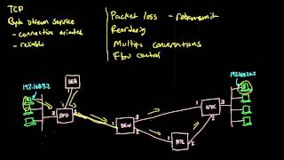
in a previous video we looked at the rs-232 serial interface standard and hooked a Serial terminal up to my breadboard 6502 computer one of the challenges of the rs232 standard is the voltage levels required you know binary 0 and 1 are represented with positive and negative 10 volts or so whereas the rest of the computer uses 5 volts for signaling so zero or five volts now in the previous video I was able to get the computer to receive data by hooking that plus or minus 10 volt signal to the gate of a mosfet which then switches on and off between 5 volts and zero volts but that only works in One Direction and indeed it does work you know I can type into a terminal program and the computer receives what I type but to be useful I want a full bi-directional serial interface that will let us truly interact with the computer so that's what I'm going to build and if you're interested in following along with this starting with the release of this video I'm selling a brand new add-on kit with all the components that you'll need to add a Serial interface to your 6502 breadboard computer and if you don't already happen to have your own 6502 breadboard computer well still selling those kits too so check out either.net 6502 for more details on both kits I mentioned the challenge we have is the computer only has a 5 volt Supply but we need to generate this positive and negative 10 volts or so in order to transmit via rs-232 well in my last video I talked about how a charge pump is this clever circuit that can double a voltage by using some capacitors and clever switching basically if you have a voltage source like this nine volt battery you'd want to double the voltage you could charge a capacitor to 9 volts then put that capacitor in series with the 9 volt battery to get 18 volts and it's a little more involved than that but so check out that previous video for more details but you can also use the same principle to generate a negative voltage roughly speaking you can charge the capacitor just like this so now this capacitor is charged to 9 volts then through some clever switching we flip the capacitor around and now it's negative 9 volts but the good news for us is that we don't actually have to build any charge pumps from scratch there's a very convenient chip specifically designed for interfacing between rs-232 and normal 5 volt logic signals and that's this the max 232 so here's the data sheet for the max 232 and you can see it says it's a dual driver receiver that includes a capacitive voltage generator to supply tia-232 voltage levels from a single 5 volt Supply It also says it operates from a single 5 volt power supply with one microfarad charge pump capacitors so that tells us it's implementing a charge pump circuit like I talked about and the operation is pretty simple got a t in pin here for transmitting and then 0 to 5 volts here is converted to a larger negative or positive voltage over here and then going the other way you've got an r in for receive coming from the rs232 interface that's either going to be that positive or negative 10 volts or whatever that voltage level is that gets converted to a zero or five volt signal here and it says it meets or exceeds the tia-232 standards so let's take a look at the you know eia 232 standard now I've been saying it's you know plus or minus 10 volts but if we actually look at the standard it says it's really it's more positive than 3 volts or more negative than -3 volts so positive voltage indicates a zero a negative voltage indicates a one but it also says down here that shall not exceed 25 volts in magnitude so anywhere from you know positive 3 volts to 25 volts is a zero and anywhere from negative 3 volts down to negative 25 volts is a one now if we look back at the max 232 data sheet it shows that it will typically generate something like 7 volts or negative 7 volts which will work because that's you know within that range and it guarantees a minimum of at least 5 volts for the positive voltage or at least as negative as negative 5 volts so that does indeed meet or exceed the tia232 spec and then for the receiver the threshold for a high voltage is uh you know typically above 1.7 volts or or at worst case above 2.4 volts and the threshold for a negative voltage is below you know typically 1.2 volts or worst case below uh 0.8 volts anywhere below 0.8 volts so that's actually very permissive and this actually characterizes a general robustness principle in engineering sometimes called postal's law after John postal who is involved in creating a lot of the early internet protocols and in the original protocol for spec for TCP he lays out this robustness principle that says that implementation should follow a general principle of robustness be conservative in what you do be liberal in what you accept from others and so that's what's going on here you know the spec says plus or minus three volts anything above 3 volts is considered high anything below minus 3 volts is considered low anything between is undefined by the spec well when it's transmitting the max 232 guarantees at least plus or minus 5 volts so it's being conservative staying well outside this undefined area here in the middle but when it's receiving it considers anything above 2.4 volts to be high and anything below 0.8 volts to be low which makes it very liberal in what it accepts and it's generally considered to be a good engineering practice to be conservative in what you send like this staying outside of that undefined area and liberal in what you accept you know allowing things that are maybe just inside the line there but this can be gamed there are bad rs-232 implementations out there that take advantage of this you know they figure that well if other implementations are liberal in what they accept like this well then maybe we can get away with five volts being considered high and zero volts being considered low even though that's not what the spec allows and so you end up with cheap products out there that sort of work a lot of the time but aren't really all that reliable because they tried to save a buck by hoping whatever you plug into them will be permissive enough but we're not going to do that and as you can see the max 232 chip will give us a good robust rs-232 interface so let's see what it takes to hook up the max 232. I'll stick it in the breadboard here and if we look at the pin out for it you can see it's pretty straightforward so it's got power and ground so we'll go ahead and hook those up power goes to pin 16 ground goes to pin 15 and that's just a 5 volt power supply because that's the whole point we Supply this with 5 volts and it generates the plus and minus seven volts or so and it uses a charge pump circuit to do that but the chip itself just has the oscillator for generating the the pulses as well as the diodes for the charge pump you actually need to supply your own external capacitors um so it says we need one microfarad charge pump capacitors and a bunch of these pins here are for connecting those capacitors so you pretty much just kind of follow what the data sheet says in terms of how to hook up the capacitors so we've got a C1 capacitor which connects between pins one and three there's C2 between pins four and five and then there's the charge pump storage capacitor so there's one for the positive voltage which goes on pin two from pin two to ground and then there's a charge pump negative or negative charge pump storage capacitor and that goes on pin six so between pin six and ground so those are all the capacitors you need and the operation is pretty straightforward right at this point we've got our transmit and receive so transmit in transmit out receive in receive out going to and from the rs-232 interface and our logic levels here and there's actually two uh pairs sorry if it's a dual driver receiver so there's a two transmits two receives and so you can see T1 in and out R1 in and out for both T1 and T2 in and out and so probably the easiest first thing to do here is I've already got uh Steve hooked up here so let's just start by moving that over to the max 232 so we'll basically just be using this part of it the receive in and then receive out so receive in is coming from the rs-232 interface and R1 in is pin 13. so let's hook that up to pin 13 right there and then R1 out is pin 12. so we hook pin 12 up to our personal interface adapter here and now we've basically just replaced this mosfet circuit with the max 232 so it'll convert the positive and negative voltages of the rs-232 signal here into 0 to 5 volt logic signals we can get rid of the rest of this stuff so let's actually try that out the functionality should be no different than what we had before so if I reset this and start typing something into my terminal look at that it works just like before but of course that wasn't the hard part the receive wasn't the hard part as you saw we were able to do that with just a simple mosfet the whole charge pump thing comes into effect when we're trying to transmit but that too should be pretty straightforward we just take a logic level off of our versatile interface adapter go into the transmit in on you know one of these and then transmit out goes out to the transmit pin on our rs-232 so transmit data is pin 2 on the rs-232 interface connect a wire to pin two so this is our transmit data coming from the rs-232 interface and of course it's called transmit because the dce in this case the 6502 is doing the transmitting and that's going to go to the T1 out so that's this pin here all right so that's T1 that's T out T1 out in this case going to the rs232 and then T in is going to come from our versatile interface adapter so T1 in is pin 11 and we'll just connect that to a pin here that we can use for transmitting and so with the max 232 chip the interface to rs232 is really just that simple we've got two logic level data lines here transmit and receive and this chip does all of the level shifting and everything we need to drive the rs-232 and as you can see we can receive data on the computer but in order to transmit we've got to write some code so let's go ahead and do that so here's what we've already got from last time for receiving so we start out by sitting in a loop here waiting for a start bit then we Loop through eight bits uh rotating each bit into the a register once we've got it we print out whatever we've got in that a register and then loop back up here to receive another byte and then you know once we receive that start bit you know we have to be very careful to read each data bit at exactly the right time because the sender is sending data at 9 600 bits per second and that's why we have this bit delay routine that we're calling before reading each bit and so 9 600 bits per second means one bit approximately every 104 milliseconds so in the previous video we figured out with you know everything else we're doing here in this bit delay routine we basically need to sit in this little Loop 13 times to get it so it takes exactly 104 milliseconds between when we read each bit and when we transmit we're gonna have to do something very similar except of course instead of reading bits we're writing them so we've got the transmit pin hooked up to this pin here which is the first bit of Port A so the first thing we can do is set it High by putting a 1 in the a register and writing the a register to Port A setting it to one will output 5 volts on that pin which the max 232 will translate into negative 7 volts or so and the negative voltage is the idle state for rs-232 so we want to initialize it like that now to actually send a character we need to flip that pin on and off for each bit and to do that I'm going to use the trb and TSB instructions trb is test and reset bit and TSB is test and set bit and if you look at TSB what it does is take the a register or it with with whatever's in some memory location and then put the result back into that memory location now you know memory location could be anything that's addressable by the processor it doesn't actually have to be in Ram so I'm going to do this with port a so if I load a 1 into the a register and then do test and set bit port a let's look at what that does also we've put a 1 into the a register which is just going to be all zeros and a one and then port a is you know this port here and we're only interested in this last bit here um which you know is the least significant bit it's all the way on the left here physically um it's this bit here the other uh parts or the other bits in Port A we could be using for something else we don't really want to disturb those so the TSB command what it does is it takes whatever's in the a register which is just that one bit it ORS it with port a so you know zero or something is just going to be that something so 0 or 1 is a one zero or zero is a zero so it doesn't change any of these bits that are zero and then the one or with anything is going to be a one right one or zero is a one one or one is a one so either way that's a one so what it does is it takes whatever's in the first seven bits of of Port A leaves those alone and then sets the last bit to one and then writes that out to Port A which has the effect of you know whatever this uh port a was it flips that last bit on whether it was on or off it's now going to be on so that sets this bit on If instead we do test and reset bit port a let's see what that does so test and reset bid or trb takes whatever's in the a register it inverts it that's the little squiggly and then it ends it with what's in that memory location that we give and like port a in our case and then it puts the result into port a so if we look at that we've still got that one in the a register and then port a we say well we don't really care we don't want to do anything with the first seven bits and then the last bit we want to flip so we invert a so instead of 0 0 1 we get all ones followed by a zero and then we and those two so anything and one is just going to be what we started with right one and one gives you one zero and one gives you zero so we don't touch the first seven bits but the last bit because we've inverted a we're now ending that whatever's that that bit is currently set to we're ending it with zero so that's always going to give us zero so the trb is going to set that bit to zero so we've got test and set bit which sets the bit on and test and reset bit which resets the bit to off or zero and so that makes it very easy to toggle the transmit pin as needed you know these are newer instructions that weren't in the original 6502 but they're very handy and actually send a character we're already using the a register here for this bit mask so let's put the character to send in memory somewhere we'll send uh I don't know an asterisk let's say and then put that into address zero two zero zero hex which is just somewhere in Ram that I'm picking arbitrarily then to start sending the character we need to start with the start bit which means coming out of the idle state where we were you know holding the transmit pane high and instead bring It Low so we'll use the test and reset bit which will set that low and then after setting the start bit we need to Loop through all eight bits of the character so let me Define a loop here so we'll use the X register to count down from eight then we'll decrement X each time through the loop then Branch not equal so if x isn't zero yet then loop back up to the top of our Loop which will label as right bid so now whatever we put in here will happen eight times and then as for what we put in here remember we have to make sure that we transmit each bit 104 milliseconds apart in order to be sending data at 9 600 bits per second so we need to make sure that whatever we put in here this Loop takes you know 104 milliseconds and the content shouldn't be too different from our byte receiving Loop down here except of course we're transmitting instead of receiving so for now let's start by just using the same delay subroutine it might not be exactly right but at least it should get us pretty close and we can adjust it later if we need to and now we need to figure out what the next bit to send is going to be so remember we put the character to send into memory location zero two zero zero here so if we rotate right it'll rotate the rightmost bit into the carry flag and rotate all the other bits to the right as well so each time through this Loop we'll get the next bit put into the carry flag it's now depending on whether the carry flag is set or not we can send a one or a zero so we can Branch if carries set to send one otherwise we'll drop in here we'll rescind a zero then send one is here where we can send a one and then if we send a zero we need to jump down to the end because we're done transmitting this bit and like we saw before sending a zero or a one is is straightforward to send a zero we use the test and reset bit instruction to reset a bit and to send a one we use the test and set bit to set a bit and that should pretty much do it for sending a byte we've got this Loop here so down through here that sends eight bits and we just need to wrap up with the stop bit which means pulling the transmit pin high again so that it's back to its idle state we just also need to make sure that we wait before doing that because we'll have just sent the last bit so let's add a delay before the stop fit and we should probably also add a delay here after sending the stop bit before we do anything else so I think that should do everything we need to send a character over the serial interface so let's save this assemble it and give it a try by reprogramming the eprom with this new code I'll put the eprom back in and then let's look at a scope up to that output interface here and then I'll hook the the other probe up to the rs-232 transmit pin so this should be the voltage shifted one and if I reset the computer look at that and we've got a signal that we're sending and if you look at the serial terminal program that I've got plugged in here you can see we're receiving the asterisk actually each time I reset the computer it should send another asterisk so there it goes and after it sends the asterisk if I type anything into the terminal program you can see the computer receives it just like before so now we're able to transmit and receive using a Serial interface and then you know what we're seeing on the scope is basically just what we program we start off high and then we go low for the start bit and then the data bits are either high or low depending on what data we're sending and then we go high again for the Stop bit and remain idle and the output of the max 232 chip is doing exactly what we'd expect when this is high it's bringing the output to the negative voltage level and when it goes low it brings it to the positive voltage level so here's zero and you can see it's kind of plus or minus what is this five volts per division so it looks to be about plus or minus seven volts as advertised but there are a lot of limitations to what we're doing here you know for one the timing is really sketchy you know we're using this bit delay which you know I guess it kind of turns out that it worked out well enough you know if you look at the scope here each of these divisions is 200 microseconds and you know this each one or zero needs to be 104 did I say milliseconds before I meant microseconds 104 microseconds and so it's you know about right so that just kind of worked out we don't need to tweak that obviously it's working we're receiving the asterisk but we're relying on this bit delay Loop down here to to make that work which means it's not all that simple to change speeds like if we wanted to go from 9600 to 57 6 that would get kind of tricky but an even bigger issue is that in order to transmit or receive that's all this processor can do you know during the time that we're spending here in this bit delay Loop or you know any of these other routines here where we're transmitting or receiving the processor can't do anything else useful and that includes receiving data while we're transmitting you know because we're we're transmitting here we can't simultaneously receive data you know we're transmitting this byte here then we drop down to our receiver team but rs-232 is a bi-directional interface you know we've got two wires here for a reason it can and it can certainly operate in full duplex which means data can be both sent and received in both directions at the same time and you know as you can imagine trying to write software to handle that would be challenging so ideally we don't want to do all this low-level serial Communication in software fortunately we don't have to it turns out they make specialized Hardware that handles timing and bit by bit transmitting and receiving and here's an example this is a universal asynchronous receiver transmitter or uart and it'll let us really simplify our serial interface and that's what I'll be doing in the next video and again if you're interested in following along with that I'm now selling this kit with all the extra bits for the serial interface including the uart the max 232 a Serial uh nine pin connector and other components and I should be shipping these in about a week or so after this video is released and of course the 6502 computer kit and everything else is all still available as well over at either.net shop so check that out if you're interested otherwise as always thanks all my patrons for helping make this video possible
Original Description
Support these videos on Patreon: https://www.patreon.com/beneater or https://eater.net/support for other ways to support.
------------------
Social media:
Website: https://www.eater.net
Twitter: https://x.com/beneater
Patreon: https://patreon.com/beneater
Reddit: https://www.reddit.com/r/beneater
Special thanks to these supporters for making this video possible:
Adrien Friggeri, Aleksey Smolenchuk, Alex, Alex Black, An Dương, Anthony Weems, anula, Ben, Ben Cochran, Ben Williams, Bill Cooksey, Bill Watkins, Binh Tran, Богдан Федоров, Bradley Stach, BRian Haug, Burt Humburg, Carl Fooks, Carsten Schwender, Chai, Chris Anders, Chris Lajoie, Chris Sachs, criis, Cristi Cobzarenco, Daniel Jeppsson, Daniel Pink, Daniel Tang, Darrell Burgoon, Dave Walter, David Clark, David Cox, David Dawkins, David House, David Sastre Medina, David Turner, Dean Bevan, Dean Winger, Deep Kalra, Dennis Henderson, Dennis Schubert, Dilip Gowda, Dirk Sperling, Dmitry Guyvoronsky, Dušan Dželebdžić, Dustin Campbell, Dzevad Trumic, Emilio Mendoza, Eric Dynowski, Erik Broeders, Erik Granlund, Ethan Sifferman, Eugene Bulkin, Evan Serrano, Evan Thayer, Eveli László, EvinSaysMarxWasRight!, Florian Bürgi, fxshlein, George Miroshnykov, ghostdunk, GusGold, Hovis Biddle, Humberto Bruni, Ingo Eble, Ivan Esparza, Jack McCracken, Jacob Ford, James Beldock, James Capuder, Jared Dziedzic, Jason Bowen, Jason DeStefano, Jason Grim, Jason Thorpe, JavaXP, Jaxon Ketterman, jemmons, Jeremy Cole, Jesse Miller, Jim Kelly, Jim Knowler, Joe Beda, Joe Pregracke, Joe Rork, Joel Miller, Joey Murphy, John Hamberger jn., John Henning, John Meade, Jon Dugan, Jonn Miller, Joseph Portaro, Jurģis Brigmanis, Justin Graziani, Kai Wells, Kefen, Ken Paul, Kennard Smith, Kenneth Christensen, Kyle Kellogg, Lambda GPU Workstations, László Bácsi, Leo K, Lithou, Lord Dorogoth, Lukasz Pacholik, Marcos Fujisawa, Marcus Classon, Mariano Uvalle, Mark Day, Martin Noble, MatrixSenpai, Mats Fredriksson, Matt Krueger, Matthäus Pawelcz
Watch on YouTube ↗
(saves to browser)
Sign in to unlock AI tutor explanation · ⚡30
Playlist
Uploads from Ben Eater · Ben Eater · 57 of 60
1
 2
2
 3
3
 4
4
 5
5
 6
6
 7
7
 8
8
 9
9
 10
10
 11
11
 12
12
 13
13
 14
14
 15
15
 16
16
 17
17
 18
18
 19
19
 20
20
 21
21
 22
22
 23
23
 24
24
 25
25
 26
26
 27
27
 28
28
 29
29
 30
30
 31
31
 32
32
 33
33
 34
34
 35
35
 36
36
 37
37
 38
38
 39
39
 40
40
 41
41
 42
42
 43
43
 44
44
 45
45
 46
46
 47
47
 48
48
 49
49
 50
50
 51
51
 52
52
 53
53
 54
54
 55
55
 56
56
 ▶
▶
 58
58
 59
59
 60
60

KA 60 Minutes Sep 2013 rerun (10x speed)
Ben Eater
Frame formats | Networking tutorial (6 of 13)
Ben Eater
TCP: Transmission control protocol | Networking tutorial (12 of 13)
Ben Eater
Clock synchronization and Manchester coding | Networking tutorial (3 of 13)
Ben Eater
TCP connection walkthrough | Networking tutorial (13 of 13)
Ben Eater
Lower layers of the OSI model | Networking tutorial (7 of 13)
Ben Eater
Hop-by-hop routing | Networking tutorial (11 of 13)
Ben Eater
Sending digital information over a wire | Networking tutorial (1 of 13)
Ben Eater
ARP: Mapping between IP and Ethernet | Networking tutorial (9 of 13)
Ben Eater
Analyzing actual Ethernet encoding | Networking tutorial (4 of 13)
Ben Eater
Intro to fiber optics and RF encoding | Networking tutorial (2 of 13)
Ben Eater
The Internet Protocol | Networking tutorial (8 of 13)
Ben Eater
Looking at ARP and ping packets | Networking tutorial (10 of 13)
Ben Eater
The importance of framing | Networking tutorial (5 of 13)
Ben Eater
Programming my 8-bit breadboard computer
Ben Eater
Programming Fibonacci on a breadboard computer
Ben Eater
Connecting to a mystery signal | Digital electronics (4 of 10)
Ben Eater
Using a transistor to solve our problem | Digital electronics (8 of 10)
Ben Eater
Inverting the signal with a transistor | Digital electronics (9 of 10)
Ben Eater
8-bit computer update
Ben Eater
Bus architecture and how register transfers work - 8 bit register - Part 1
Ben Eater
RAM module build - part 2
Ben Eater
Using an EEPROM to replace combinational logic
Ben Eater
Build an Arduino EEPROM programmer
Ben Eater
Build an 8-bit decimal display for our 8-bit computer
Ben Eater
8-bit CPU control logic: Part 2
Ben Eater
Reprogramming CPU microcode with an Arduino
Ben Eater
Update and PODCAST ANNOUNCEMENT!
Ben Eater
The case against Net Neutrality?
Ben Eater
Making a computer Turing complete
Ben Eater
CPU flags register
Ben Eater
Conditional jump instructions
Ben Eater
“Hello, world” from scratch on a 6502 — Part 1
Ben Eater
What is a stack and how does it work? — 6502 part 5
Ben Eater
RAM and bus timing — 6502 part 6
Ben Eater
Subroutine calls, now with RAM — 6502 part 7
Ben Eater
Why build an entire computer on breadboards?
Ben Eater
How assembly language loops work
Ben Eater
Binary to decimal can’t be that hard, right?
Ben Eater
Hardware interrupts
Ben Eater
What is error correction? Hamming codes in hardware
Ben Eater
Installing the world’s worst video card
Ben Eater
World's worst video card gets better?
Ben Eater
Breadboarding tips
Ben Eater
So how does a PS/2 keyboard interface work?
Ben Eater
Keyboard interface hardware
Ben Eater
Keyboard interface software
Ben Eater
How does a USB keyboard work?
Ben Eater
How does USB device discovery work?
Ben Eater
How does n-key rollover work?
Ben Eater
SPI: The serial peripheral interface
Ben Eater
Why was Facebook down for five hours?
Ben Eater
How do hardware timers work?
Ben Eater
The RS-232 protocol
Ben Eater
Hacking a weird TV censoring device
Ben Eater
Let's build a voltage multiplier!
Ben Eater
6502 serial interface
Ben Eater
RS232 interface with the 6551 UART
Ben Eater
Fixing a hardware bug in software (65C51 UART)
Ben Eater
Running Apple 1 software on a breadboard computer (Wozmon)
Ben Eater
More on: LLM Engineering
View skill →![FULLY LOCAL Mistral AI PDF Processing [Hands-on Tutorial]](https://i.ytimg.com/vi/wZDVgy_14PE/mqdefault.jpg)


Related Reads
📰
📰
📰
📰
How to Write SQL Queries That Detect Unstable Join Filtering and Inconsistent Results
Medium · Machine Learning
How to Write SQL Queries That Detect Unstable Join Filtering and Inconsistent Results
Medium · Data Science
Fable 5 Hype: Fangirling with Datasets to Build a Lakers Dashboard
Dev.to · L. Cordero
Imagine waking up one day only to discover your account has been suspended.
Medium · Data Science
🎓
Tutor Explanation