Build an 8-bit decimal display for our 8-bit computer
Skills:
ML Maths Basics90%
Key Takeaways
This video demonstrates how to build an 8-bit decimal display for an 8-bit computer using an EEPROM, with support for both unsigned and signed display modes. The display uses multiplexing to drive four digits using a single EEPROM.
Full Transcript
so in a previous video we used an eom as a decoder for a seven segment display so by hooking up a binary input here so this is six or you know four five by by inputting a different binary number on the address lines of the eom the eom would output ones and zeros in the appropriate places to turn on or off the appropriate segments on the seven segment display but how could we build a decoder for 8 Bits that outputs a number from 0 to 255 on three of these seven segments displays and that question came up in the comments on the video about using any eom as a seven segment decoder uh the Youtube cuber asked what do I do if I have multiple seven segment displays displaying one decimal number and uh there's some good replies in here so russle teapot says if I've got this correctly you would need one e prom for each seven segment display and that's exactly what uh what we've got here we've got one e prom for each of the seven segment displays so we've got a ones place e prom for the ones digit a 10 place for the 10's digit and hundred's place for The Hundreds digit and then the address lines or at least the first eight of the address lines for the chips are all linked together so if we put a an address value on these eight lines here in this case I'm putting the binary equivalent of 123 that same value is going to show up on each of these chips so this Chip is going to be at address 123 this Chip is going to be at address 123 and this Chip is going to be at address 123 and so at that address for the hundred's chip it's programmed to display a one that address for the 10's chip it's programmed to display a two and the ones chip is programmed to display a three and and then they go on to say let's say we want to represent the numbers from 0 to 15 we can use two e Proms and this is this is exactly right here so this shows for the the address 0 through 9 uh that first e prom is just outputting all zeros and the second one outputs the numbers from 0 to 9 and then it it wraps around here uh and that first e prom now outputs a one for uh 10 through through 15 and then Jason Masters here says kind of restates that and and then says yeah if you link the address lines of of the chips together so all the chips get the same address and you put the binary number on the address line and the output of the chips will display the decimal equivalent that's that's uh yeah that's absolutely right so simple um but then this is this is interesting the the YouTube CU again says another thing that I thought of is multiplexing through the eom so you get the binary number and the digit number as input and then you get a you know binary code a decimal or I guess you'd get the um decoded seven segment thing as as your output and it says you need a binary counter on the digit number input to start multiplexing I like this idea rather than needing to have three of these e proms one for each digit we can do it with a single eom that drives all three digits now it's going to be a little bit more complex but it's uh I don't think we're going to need to do anything that we haven't already done elsewhere in our computer build so let's give it a try and I'll explain more about how this multiplexing works as we as we build out the circuit so this dis display module is going to be part of our computer it's going to be the output for our computer so I'm going to connect a new breadboard here right below the B register for our computer and build the display output here and so we're going to use a single eom that's the the idea of this multiplexing idea the 20 hc16 and I'll start by connecting it to a a single seven segment display and this is a a common cathode uh instead of common anode which were the ones we were using before so I'm going to connect the common cathode here to ground through this 330 Ohm resistor and there is a reason I'm using a common cathode display here which I'll go into later and so I'm just going to connect the eight output pins for the eom to the seven segments of the of the seven segment display plus the the decimal point and I realize it's kind of hard to follow with everything on top of each other there but basically what's going on is we've got these IO pins IO 012 3 4 5 6 7 those are the pins that are connected here and they're connected to the seven segments of display basically like this so you know this is what our seven segment display is going to do just 0 through 9 CU we're just doing decimal at this point and each of the segments has a letter designator so A B C D E F and then G is the one in the middle and then of course there's also the decimal point over here and so this is the way that I've arranged the the bit order so the decimal point is the most significant bit so that corresponds with io7 here and then it goes a b CDE e f g where G is the least significant bit corresponding with io0 over here so that's that's how I've hooked this up um but of course you can hook it up any way you want you just got to make sure you know which bits need to be on for each of the numbers that you want to display and now we can also hook up power and ground for the eom so that uh it's powered and then the control signals that we've got we've got our chip enable our output enable and our right enable at chip enable we want that to be active so that's active low output enable we also want to be active and that's that's also active flow and then write enable we don't want that to be active we don't want to be writing to this and so that's active low so we want to tie that high so that we're not going to accidentally write anything to this chip and so that leaves just the address lines so there's eight address lines over on this side and then address 8 9 and 10 over on that side and for now I'm just going to temporarily tie those all low and so that's the first eight address lines are all tied low there and then I'll also tie the remaining three address lines over here low as well so with all the address lines tied low this Chip is going to be addressing address location zero and we'll see whichever bits are set on the output here so let's add power and we can see that we're getting all of the bits set so all seven segments plus the decimal point are on so address location zero on this chip is apparently programmed with with all ones and if we go to some other address so address one two so it looks like this chip is probably erased if all it's giving us is all ones on the output so let's pull the chip out and and program it with something so I've got the e prom in our Arduino programmer and I'm going to come over to the coat here and because we're using a common cathode display now instead of a common anode I'm going to make sure I've got the right programming for that so this is the the right bits that we want to have set for common cathode so I'm going to go ahead and upload that and look at my serial Monitor and so it's programming and okay it looks like it's going to start by erasing the eom and then it programmed it and looks like it's got that program in there for the first 16 bytes okay so let's pull it out and put it back in our other circuit so we put this back in here now and connect power so now we've got a zero and if we go to address location one we've got a one and this is working as we would expect but of course we want to have more than one digit and so the way the multiplexing is going to work is we're actually going to drive all of the digits using the same data bits and then we're going to switch on certain digits at certain times which will hopefully make more sense in a minute here so I'm going to add a couple more digits here and what I'm going to do is I'm going to connect all of these essentially in parallel so that the outputs of the eom go to all of them in the same way so I've hooked all of the pins for the segments together so if we connect the the common cathodes for each of these to ground we should see each of the digits light up the same way assuming everything is connected properly which things are getting pretty crowded down here so let me see what's going on here there we go and so now if I change the input all three of these digits should change so there's one three two and so on so of course this isn't what we want but it does mean that we can control all of these digits from the one chip and actually I've got a little extra room over here so I can add a fourth digit if I want and I think there might be a way to use it cuz I think there will actually be a use for that fourth digit which I'll get into later but now what we need to do is build the multiplexing logic that Cycles through each of these digits so we can display a different number on each digit and a sequence that we need a clock and I don't want to use the clock that is running the rest of the computer because we might want to run that at a different rate or whatever so I'm going to build a separate clock just for the output display using a 555 timer so let me connect a 555 timer over here I'll connect ground and power and then I'm going to connect a 2 microfarad capacitor from pin two to ground I'm also going to connect pin 2 over to pin six pin five I'm going to connect to ground with a 10 nerad capacitor and I'm going to put a 100K resistor between pin 6 and 7 and then a 1K resistor between pin 7 and uh and 5 volts or between pin 7 and 8 I guess pin 8 is already connected to 5 volts and so this is a simple aable configuration for the 555 timer and if I hook the uh the output which is pin 3 up to an LED which is going through a resistor to ground I should be able to see this pulsing so if I connect power there we go so we have a little clock running here and so next what we want to do is we want to use this clock to sequence through each of our displays and to do that what we need is a small counter so the 74 LS 76 has got two JK flip flops on it which is just enough to make a uh simple two bit counter and we basically want to take advantage of the toggle functionality of the JK flipflop to build a simple counter so we want to basically just connect the preset clear J and K inputs all high and then just use the clock and every time the clock pulses we'll get a toggle and we can use that to build a counter so this is the preset and clear for the first flip-flop tying both of those high as well as the J input and the K input so those are all tied high and then also the preset and clear for the second flip-flop as well as the J and K inputs for the second flip-flop and then of course the this chip also needs power and ground to power the chip so next we can connect the clock into our clock input for one of our flip flops and then we'll connect the output of that flip-flop into the clock input of the other flip flop to create a counter so we'll connect the output of our 555 timer to that clock for one of the JK flip flops then I'll connect an LED to the output of that flip-flop and also connect the output of that flip-flop around to the clock for the other flip-flop and finally I'll look at the output of the second flip-flop so now if we power this up hopefully we'll have a working counter and it looks like we do so we've got this counter now so it's counting from 0 1 2 3 0 1 2 3 so that's counting from 0 to three and so we can use that count to control which of our digits we want to display and to control that I can use two of these additional address lines so remember we've got our eight address lines down here that we're using to input which value we want to show so right now we're inputting a two and we're seeing twos but we've also got these three additional address lines up here that we're not using they're all tied to zero well we can tie two of those to these these counting uh LEDs over here so instead of tying this address line to ground I can tie it to this led here and instead of tying this to ground I can tie it to this led over here and what you see is that when both of these are zero we see the same thing we saw before we see that two so once every four clock Cycles essentially we get a two here and then the other times we're getting just all eights with the dot so basically all of the bits are set but what we could do is program this so that when the counter is at zero it's outputting the number we want in the ones place and when the counter is one it's outputting the number we want in the 10's place and when the counter is two it's outputting the number we want in the hundred's place so let's go ahead and actually program the e to do that so again I'm going to put the eom into our Arduino eom programmer and so just to summarize what we're trying to do here we've got these 11 address bits and we're using the bottom eight of them a0 through A7 to input the number that we're trying to display so this could be anywhere from all zeros to all ones so 0 to 255 and then we're using address 8 and address 9 to tell us which digit we wanted we want to display so if these are both zeros then we want to display the ones place and so if we put in for example if we put in the number 123 here we'd want the output to display a three but if we set A8 high if we put in zero and a one for A9 and A8 then we want this to display the 10's place for that same number so again if we've got 123 let's say here then we want to display a two so that would be the 10's place and then if A9 is a one and A8 is a0 then we'd want to display 100's place for whatever is in here so again if this is 123 we'd want to display a one so again just as a as an example here this is what we would actually want to see programmed in the eom for example so it address 0000 0 and then this 0111 1 011 this is this is the binary for um 123 in decimal and so because we've got the 0 0 here the output is going to be the bits that we need to set in order to show a three but if our input is that same set of bits in the the lower eight bits so this is still representing the number 123 but in this case if we've got a 01 in these upper bits then we want to output something different we want to Output the bits that we need in order to display the number two on the seven segment display and then same thing here for the 100's place if A9 is 1 and A8 is zero and the rest of these are the same this is still representing the number 123 now we want to Output whatever we need to Output to display the number one this case it's just these two segments and then you know because we've got four digits uh there is also this case that we have to handle where we've got a one and a one in A9 and A8 and in this case we'll just output nothing so all zeros will just mean none of the segments are on so that fourth display will just be blank so this is what we want to program so we don't really want to just type out all of those because that's that's going to be you know over a thousand separate numbers and we don't want to we don't want to type all that out like this so let's write some code that actually just fills in all of the numbers that we need to PR into the eom though I am going to use this this part here at least up to number nine yeah so this this part here I'm actually going to copy that and then we'll comment that out and then down here let's see we don't need to erase the whole eom we're just going to be writing over a lot of this anyway so I'm going to delete this code and then here where we program the data bytes rather than just programming whatever was in that data array we'll call this digits and so these are just the the hex codes that we need in order to display each of the digits from from zero through 9 and so we want to start by programming all of the ones place so we can go from address 0 to 255 and we'll do write WR eom address and then we want the the digit that corresponds to the ones place for that address so to get the ones place of the address we can do address mod 10 and this percent sign is the modulo operator which essentially just divides address by 10 and gives you the remainder so so if address is zero we divide by 10 the remainder is zero if the address is 123 we divide that by 10 we get 12 with a remainder of three and so it'll you know so this this will give us three which is the one's place in 123 so this will give us whatever the value of the ones place is for address but we we don't want to write that we want to write the uh the digit for that so what we can do is we can just use this as an index into digits so if we say digits and then at that index cuz this this address mod 10 is always going to be a number between 0 and 9 because whenever you divide something by 10 the remainder is going to be between 0 and 9 uh so that's always going to be a number between 0 and 9 and so that's just going to give us whichever of these values corresponds with that position so this should write all of the ones places to the eom next we need to write all the 10 places so we'll go from 0o to 255 and actually address is probably not the best name for this let's call this value because the value and the address are are only the same for uh the the ones place so I'll just rename all of these value to be consistent and so here we're going to write to Value Plus 256 is the address that we're going to write to and that's because we're doing this case here where we're doing the the 10's place and so A8 is always going to be set and the value the place value of of this bit is 256 so it's going to be whatever the value is plus 256 and that's the where we want to program the 10 the you know the the appropriate code for the 10 place and so here we want to get the 10's place and so if we do address or Not address value oops actually this should be value mod 10 so if we do value divided 10 because value is declared as an integer here this divide by 10 will be an integer division so it won't give us a decimal place it'll just give us a truncated value so if it's 123 and we divide by 10 it'll just give us 12 it won't give us 12.3 and so if we take that and then we do a mod 10 we'll get the two for the 10's place and so again we can use that as an index into digits to get the appropriate code to display that digit so we'll write that and then we want to do the hundred's place and it's going to be the same thing we'll just go through all 256 values and in this case the offset is 512 because we're writing now to to this range here where A9 is set in A8 is not set and and the place value of in binary of A9 is 512 so we just make sure we just add that to whatever our value is to put it in that address so value + 5 12 and then digits we're going to index into digits for Value divided by 100 to get the hundred's place and then mod by 10 although that's probably not going to be necessary because we're only going from 0 to 255 so there should only be Z one or two but we can do that anyway for consistency and so this will write all the 100th place and then for that fourth digit because we do have four digits we just want that last one to be blank so we can do a loop that just uh writes all zeros to that range so this will be Value Plus uh 768 because both uh A9 and A8 are set so you take the 256 plus the 512 and you get 768 and then for that whole range we're just going to write all zeros because we don't want that digit to display anything we'll just write all zeros and we don't need this Loop to write our data so we'll do that and then yeah we can still print uh the output there so let's upload that and it's programming and it's done and well we just printed the first 255 bytes here but you can see this should just be repeating the that first 10 uh things over and over again and it looks like it maybe is but uh yeah let's give this a try let's pull this out and put it into our circuit so get the eom back in the circuit hook up power and we see it cycling through two Z and blank but of course it's not putting the numbers onto the individual displays it's just showing them in sequence which is not quite what we want but we're getting there and so if we give this another uh another number so let's say we give it that example like that 123 and you see 321 blank 321 blank and so what we want is we want the three here the two here the one here and the blank there so what we need is some way to sequence through these dis displays and for that what I'm going to do is I'm going to use our counter to then feed into a decoder so to do that I'm going to use the 74 LS1 139 which is a 2 to four line decoder or D multiplexer and so what it does is it's got two inputs A1 and B1 and depending on what those values are you get one of these data outputs uh goes low and so basically you can imagine this this A and B we're going to use our counter here which is counting from Z through four in binary we're going to use that A and B and it's going to cycle like this from both being low to a being high then B then both so that that's what we've we've already got that and then what happens is the outputs it just cycles each of these going low in turn so it just Cycles through each of those and then what we can use this to do is is Select which output digit we're displaying and the way this chip works is pretty simple it's got the two inputs and it's essentially just using a series of and Gates and inverters to pick based on how these inputs are set which output to turn on so if we po the 74 LS 139 up here it's pretty simple to hook up we just need to give it the power and ground like we do with all of these and then it has an enable pin here uh pin 15 that's active low so we want that to be active so we'll tie pin 15 here to ground and then the inputs are just pins 14 and 13 and I'm just using this top one because coming from from over here so just stay on that side of the board so I'll just hook these two to those inputs so now let's take a look at the outputs which are on pins 9 10 11 and 12 and so you can see the outputs of this decoder uh you've got all of the outputs on except for one and the one that goes off corresponds to our input as we're counting this is very convenient and this is also the reason that I used the common cathode displays because what we can do is we can hook these outputs up to the cathodes here rather than just tying all the cathodes to ground and that way the only cathode that will actually be hooked to ground will be the one that we want to be displaying for example instead of connecting the on Place cathode directly to ground through this resistor if I connect it to this first output here you'll see the ones place is only on when we're displaying that three and the three is what should be in the one's place so in other words we're both displaying the correct digit and putting the correct address into the eom to display that place value at the same time and so I can do the same thing for the 10's place instead of connecting that directly to ground through that resistor I can connect it to the second thing here and so now you see the one the 10's Place only shows up when we have a two there and remember the input here is is 123 so we get the two in the 10's place we get the three in the On's place just as we should and then the hundred's place same thing rather than connecting that directly to ground we can connect it to this place here and so now we only see the one when we're addressing the location in the e prom for the 100's place then finally this fourth digit we can do the same thing although we shouldn't see much there because remember we programmed all zeros into that last block of memory and so now we've got the right digits in the right places but this isn't quite what we want right because we want our display to actually show us a number we don't want to have to read it like this this is kind of kind of janky but what we can do is adjust the speed of our clock and so if I replace the uh the 100K resistor with a 100K potentiometer I can start to increase the speed by turning that potentiometer and what you'll see is as it gets faster and faster it looks more like 123 and if I go fast enough you can't even tell that it's flashing like that and so that's basically our display now instead of sticking this pot in here I'm going to put the 100K resistor back so now another way to slow this down is instead of using this 2 microfarad capacitor I'm going to replace that with a 10 narad capacitor instead and that's going to give us a similar uh kind of effect and with it running this speed we don't really need any of these LEDs they're not showing us anything interesting so I'm going to pull those out as well also going to clean up these wires here and just replace them with wires that are cut to length and so there we go we've got our eight inputs here and we can switch these to different values and we get the decimal representation of whatever input is down here on our display now we've also got this last address line that we could do something interesting with so right now if we take that high we just get all ones on everything because we haven't programmed the other half of this chip so we could actually have two different type of display we could program the first half of the chip the way we have for a decimal display and then the second half of the chip could be programmed with some other kind of display could be hexadecimal if you want to do that um or what I think would be interesting and since we have this fourth digit is you could program the second half of the chip to show negative numbers or or more specifically you could you could have it decode two's complement numbers which could be positive or negative tw's complement uses an 8-bit number to represent numbers from between 120 up to positive 127 and so we could use this first digit to show the negative sign if we need to so to display in in two's complement we want to basically do the same thing but instead of you right now we're programming values from or we're program memory locations essentially from zero through uh 1023 because this is going to be 255 + 768 is 1023 so we're programming essentially the whole first half of the chip with our our normal uh unsigned integers and so for the signed integers that use the the tw's complement we're going to start at uh memory location 1024 so to program that we're going to want to go value from 128 oh you know what I just realized we might have a bug here because look at this we're going from zero to Value less than 255 so we might not actually be programming 255 so let's let's actually give that a try let's go back here set this to here and let's try looking at position 255 I bet it's not programmed properly so if we go to let's see that's 254 and if we change this to one yeah look at that we didn't program 255 because we said less than 255 so we need to do less than or equal to for all of these so I'm glad I caught that now if we come back down to here so our value is going to go from negative for two's compliment our value is going to go from negative 128 to positive 127 and again our our address is going to start at 1024 um but we don't want to just add value to it right because value starts at -28 so if we add that to 1024 we're actually going to be writing uh partway into into this uh area before so what we can do is we can take a value and cast it to a bite and what this will do is it will take uh value and treat it as an unsigned bite so if it's if value has -28 in it then this will say Wella 128 is represented as a bite as one followed by seven zeros because that's how you know because this this is going to use two's complement to represent that so this should take value and and using a a two's complement convert it to an 8bit bite uh which which should be a positive number and then we'll use that as our as our address and then what we want to write there is essentially the same thing as we have here digits uh for value mod 10 but what I want to do is I want to take the absolute value of this uh so if it's you know if it's -23 then this will take the absolute value of that and give us 123 before we uh mod by 10 and look at the last digit and so now we can move on to the 10's place again it's going to go from 128 to 12 or negative 128 to 127 and basically the same thing but of course we're going to divide value by 10 first to get the 10's place and our base here instead of being 1024 is going to be 12 80 right it's 1024 + 256 and then for our hundred's place we can just copy this again and so this will be divide by 100 to get our 100's place and this will be uh 1280 + 256 which is uh 1536 and so that'll be our hundred's place and then we just need to do that fourth digit there which uh before we just set to all zeros but in this case we could use that to represent our sign by setting a negative sign there and so what we want to do is if if our value is negative so if value is less than zero so if it's negative then we want to write to our address so it's take value and cast it to a bite to get a positive two's complement representation of of our value and then here our offset is going to be 1536 + 256 which is 1792 and so if it's negative we want to write uh I believe a one right so one should be this should be the one the that last bit should be seg G which which is the one in the middle that that would look like a negative sign um and otherwise if it's non zero we want to write to that location plus 1792 uh in this case we just want to write zero uh we just want the display to be blank if it's positive and I think that should do it yeah and I'm going to add one other thing is I'm just going to add some uh some print lines here so we can uh just keep track of what it's doing while it's programming because it's programming the entire e prom where we're programming all all 248 memory locations in the E promp so it's going to take a little while so I'll add these print lines so that it's easier to see what's going on okay so that should be it so let's go ahead and upload this look at our serial Monitor and this is taking a little while I'll speed this up for you and it's done so let's pop the eom back in our circuit here so we've got our 255 here so that's fine um and so this should work just just normally so you know if we set some other values here 127 or you know 1232 123 so this is this is working normally um and these values obviously are lower than 128 but if we go up to you know 251 that's going to be positive so because we've got this bit low but if we want to look at our two's complement then we set this bit high now we're looking at two's compliment so anything below 127 or 12 28 uh should be the same so any of these other values should be the same but if we set this High bit now to something now we've got a negative number so this is -3 so let's see if we're in binary and we put in 1 1 1 1 0 0 1 1 in binary we convert that to decimal we get 243 and so that would be normally what it is so if we go to our normal mode so yeah that's 243 if we go to two's complement yeah 13 so that's right so we are getting we are getting the right thing and we can try some other things let's just I'm just going to move these around to just sort of some random things so we've got - 46 in there I don't know -62 let's say uh so this is uh 1 1 0 0 0 0 1 0 uh so if we go to decimal yep -62 and then if we're in unsigned mode that should be 194 yep so it looks like this is programmed right and working so now we've got an option where if we set this low we have a normal sort of unsigned mode so this this will just represent numbers from 0 to 255 but if we set this High then our output will show us numbers from -28 up to 127 and depending what we're using the computer for we may want one of those output modes or the other and we can set that using this this input here so I think that pretty much does it for our 8bit display here so we've got 8 Bits coming in and we're able to display either is a signed to's complement or unsigned and we did it with only a single 28 c16 e prom so I think that's quite an improvement over the last time I built one of these where I used three of these one for each digit and we've got a uh a tw's compliment signed mode as well
Original Description
In this video, we'll use an EEPROM (28C16) to create a decimal display for an 8-bit value. The display uses multiplexing to drive four digits using a single EEPROM. As a bonus it supports both unsigned and signed (twos complement) display modes.
Support me on Patreon: https://www.patreon.com/beneater
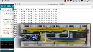
The code used in this video for programming the EEPROM is available here: https://github.com/beneater/eeprom-programmer/blob/master/multiplexed-display/multiplexed-display.ino
See https://eater.net/bbcpu8-output-register for more info.
Parts list for the finished decimal display:
- 1x 28C16 EEPROM
- 1x 555 timer IC
- 1x 74LS76 (Dual JK flip-flop)
- 1x 74LS139 (Dual 2-line to 4-line decoder)
- 4x Common cathode 7-segment displays
- 1x 1k resistor
- 1x 100k resistor
- 2x 10nF capacitors
Watch on YouTube ↗
(saves to browser)
Sign in to unlock AI tutor explanation · ⚡30
Playlist
Uploads from Ben Eater · Ben Eater · 25 of 60
1
 2
2
 3
3
 4
4
 5
5
 6
6
 7
7
 8
8
 9
9
 10
10
 11
11
 12
12
 13
13
 14
14
 15
15
 16
16
 17
17
 18
18
 19
19
 20
20
 21
21
 22
22
 23
23
 24
24
 ▶
▶
 26
26
 27
27
 28
28
 29
29
 30
30
 31
31
 32
32
 33
33
 34
34
 35
35
 36
36
 37
37
 38
38
 39
39
 40
40
 41
41
 42
42
 43
43
 44
44
 45
45
 46
46
 47
47
 48
48
 49
49
 50
50
 51
51
 52
52
 53
53
 54
54
 55
55
 56
56
 57
57
 58
58
 59
59
 60
60

KA 60 Minutes Sep 2013 rerun (10x speed)
Ben Eater
Frame formats | Networking tutorial (6 of 13)
Ben Eater
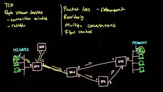
TCP: Transmission control protocol | Networking tutorial (12 of 13)
Ben Eater
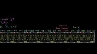
Clock synchronization and Manchester coding | Networking tutorial (3 of 13)
Ben Eater
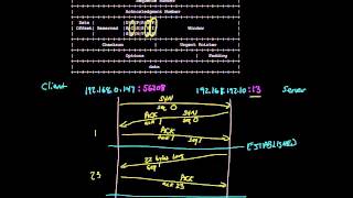
TCP connection walkthrough | Networking tutorial (13 of 13)
Ben Eater
Lower layers of the OSI model | Networking tutorial (7 of 13)
Ben Eater
Hop-by-hop routing | Networking tutorial (11 of 13)
Ben Eater
Sending digital information over a wire | Networking tutorial (1 of 13)
Ben Eater
ARP: Mapping between IP and Ethernet | Networking tutorial (9 of 13)
Ben Eater
Analyzing actual Ethernet encoding | Networking tutorial (4 of 13)
Ben Eater
Intro to fiber optics and RF encoding | Networking tutorial (2 of 13)
Ben Eater
The Internet Protocol | Networking tutorial (8 of 13)
Ben Eater
Looking at ARP and ping packets | Networking tutorial (10 of 13)
Ben Eater
The importance of framing | Networking tutorial (5 of 13)
Ben Eater
Programming my 8-bit breadboard computer
Ben Eater
Programming Fibonacci on a breadboard computer
Ben Eater
Connecting to a mystery signal | Digital electronics (4 of 10)
Ben Eater
Using a transistor to solve our problem | Digital electronics (8 of 10)
Ben Eater
Inverting the signal with a transistor | Digital electronics (9 of 10)
Ben Eater
8-bit computer update
Ben Eater
Bus architecture and how register transfers work - 8 bit register - Part 1
Ben Eater
RAM module build - part 2
Ben Eater
Using an EEPROM to replace combinational logic
Ben Eater
Build an Arduino EEPROM programmer
Ben Eater
Build an 8-bit decimal display for our 8-bit computer
Ben Eater
8-bit CPU control logic: Part 2
Ben Eater
Reprogramming CPU microcode with an Arduino
Ben Eater
Update and PODCAST ANNOUNCEMENT!
Ben Eater
The case against Net Neutrality?
Ben Eater
Making a computer Turing complete
Ben Eater
CPU flags register
Ben Eater
Conditional jump instructions
Ben Eater
“Hello, world” from scratch on a 6502 — Part 1
Ben Eater
What is a stack and how does it work? — 6502 part 5
Ben Eater
RAM and bus timing — 6502 part 6
Ben Eater
Subroutine calls, now with RAM — 6502 part 7
Ben Eater
Why build an entire computer on breadboards?
Ben Eater
How assembly language loops work
Ben Eater
Binary to decimal can’t be that hard, right?
Ben Eater
Hardware interrupts
Ben Eater
What is error correction? Hamming codes in hardware
Ben Eater
Installing the world’s worst video card
Ben Eater
World's worst video card gets better?
Ben Eater
Breadboarding tips
Ben Eater
So how does a PS/2 keyboard interface work?
Ben Eater
Keyboard interface hardware
Ben Eater
Keyboard interface software
Ben Eater
How does a USB keyboard work?
Ben Eater
How does USB device discovery work?
Ben Eater
How does n-key rollover work?
Ben Eater
SPI: The serial peripheral interface
Ben Eater
Why was Facebook down for five hours?
Ben Eater
How do hardware timers work?
Ben Eater
The RS-232 protocol
Ben Eater
Hacking a weird TV censoring device
Ben Eater
Let's build a voltage multiplier!
Ben Eater
6502 serial interface
Ben Eater
RS232 interface with the 6551 UART
Ben Eater
Fixing a hardware bug in software (65C51 UART)
Ben Eater
Running Apple 1 software on a breadboard computer (Wozmon)
Ben Eater
More on: ML Maths Basics
View skill →


Related Reads
📰
📰
📰
📰
Seq2Seq and Encoder-Decoder: the one-vector bottleneck that led to attention
Dev.to AI
UMAP: a faster map of high-dimensional data (and how it beats t-SNE)
Dev.to AI
It’s Time We Mentioned `Handover_Document.md`…
Medium · Machine Learning
AI Benchmarks and Leaderboards: Why Reliability Matters More Than Scores
Medium · Machine Learning
🎓
Tutor Explanation
