Clock synchronization and Manchester coding | Networking tutorial (3 of 13)
Skills:
Network Security60%
Key Takeaways
This video tutorial covers the importance of synchronized clocks in networking and demonstrates the use of Manchester coding to transmit binary data between two computers, highlighting its application in Ethernet protocols for clock synchronization and data transmission. The tutorial also touches on the use of GPS antennas and atomic clocks for synchronizing clocks.
Full Transcript
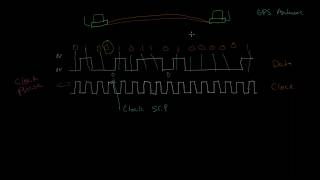
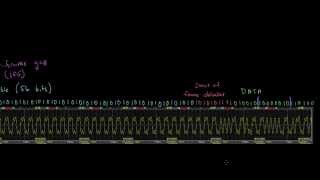
so let's say we have two computers here and we want to send some data from one computer to the other so as we've seen before we can connect a cable between them and then maybe vary the voltage across two of the wires within this cable like say between Z volts and 5 volts and Z volts is a symbol that represents a zero and 5 volts is a symbol that represents a one and so we can send some binary data this way 0 1 1 0 1 but something interesting is happening right here which is we have a bunch of zeros in a row and in order to know exactly how many zeros we have here uh we need we need to make sure that both of these computers have a synchronized clock and this is something that's actually very important uh in networking is is timing uh to make sure that both sides of these of this link agree um on a clock rate so if I add a clock rate here this is a a signal basically that just alternates between zero and one0 one0 one and what we can do is we can look at this clock everywhere it transitions from 0 to 1 that is a point at which we should read the value of the data so we have a data signal here and we have a clock signal here and so for this example here we have this whole string of zeros if we just look at how many transitions or exactly when these transitions occur from 0 to one on the clock we can see you know this transition the DAT is a one this transition it's a zero this transition is another zero this transition is another zero another zero another zero and then a one and as long as we keep track of these transitions we know exactly how many uh zeros we have no matter how long this stretch of data is as long as we have this clock but the important thing is that both sides of this link agree on the same clock so that the computer that is uh sending this data is using the same clock rate as the computer that's receiving it so now you might be wondering what happens if these two two computers uh clock signals aren't running at exactly the same speed um so like maybe maybe the receiver's computer is a little bit slow so I can show you actually what that might look like if we take that out and bring this in and actually get rid of these little transitions so this here is a clock that is running a little bit slower than um than the data was originally clocked at uh and so what you see here is that you see here's a transition and we get a zero another transition a one and these are these are actually lining up pretty well so far so this zero kind of is lining up but here you notice we missed a zero there should be a zero here and then this stuff lines up pretty well um and again we miss a zero and then things are lining up okay but here in this stretch where we had five zeros before now with a slightly slower clock we're only reading four zeros and then we have this last one here um and so the places where we're missing bits because of this mismatch I guess between transmit and receive clocks are called clock slips so this is a clock slip because we're we're basically missing a bit of information um and and then you might have the the sort of um opposite of this if the receiving clock were running faster you might actually get extra bits in there but either way we we would refer to that as a as a clock slip so this here is a clock slip and uh of course if you know if if we're missing bits like this then the the data that we're receiving um isn't isn't going to make any sense so so clearly we don't want the the two computers clocks to be out of sync like this so even if they're a little bit out of sync you know of course this is kind of an extreme example here where you know we were sending 16 bits and we only received 13 bits um but even if even if these clocks are just a little bit out of sync you know eventually over time we will have a clock slip and and that'll corrupt our message and and we would have to either retransmit our message or or somehow um figure out what happened there so it's it's important to make sure that these clocks are in sync and there are a couple ways that we can do that one way that we can make sure that clocks are in sync is actually for both of these computers to to have synchronized clocks that are either synchronized maybe through a GPS antenna so these computers would have little antennas that would connect or that would actually receive signals from GPS satellites which are the the global positioning system satellites because the GPS satellites actually have atomic clocks on board and have very very accurate clocks um and so if these computers have those GPS receivers they can synchronize their own clocks to the GPS clocks um and then know that that the clocks between the two computers are are in sync and and use those clocks for sending and receiving data um there's obviously some some disadvantages to that uh the GPS antenna is is extra Hardware so it's a little bit a little bit expensive um and you also need to be able to mount the antenna somewhere outside or or on the roof of the building or something like that but there there's definitely some Network equipment that that is in use on the internet uh that uses GPS timing uh to synchronize uh to synchronize its clock and data um so that is that is one solution another solution is actually to have an atomic clock in the computer itself um and that's it it you know occasionally uh that is done um it's fairly fairly uncommon um another approach that that you could take is if we get rid of our slow clock and bring back our normal clock here another approach that you can take is to actually send a separate signal so we have a separate uh we have like another another link or another pair of of wires between these computers where we send this clock signal so we're sending both the the data and the clock um across two different links and so that way this computer doesn't need to use its own clock it can actually receive the clock from the same computer that's sending the data so it knows that these are in sync um and there's actually a little bit of a problem with that as well or a potential problem with that which is that at as as you increase the speed that you're sending this data um these clock pulses could could actually be as as close as just a few NCS apart um and so it's very important that the clock and the data line up um because if you can imagine this clock were shifted just a little bit to the left or to the right um then these these points where the clock transitions from a zero to a one might not line up exactly with the bits um and you could misread a bit so it's very important that these stay uh lined up correctly and um and that's called clock phase phase and one of the problems with sending a clock and a data across two separate links is that it's possible that um the the you know the propagation of electrons literally across one of these links might be slightly slower um either because it takes a slightly different path or the conductivity is a little bit different if this is a long path so you tend to not want to do this on very highspeed links over uh very long distances um or or you could get into an issue where the clock gets slightly out of phase with the data and you start to misread uh some some bits so another approach that that we can take that's actually quite common is is kind of ingenious which is to combine um the clock and the data by using different symbols to represent ones and zeros so just a review um what we've been doing here is when we're transmitting our data we're we're transmitting it using two symbols and so when we want to send when we want to send a one the symbol that we're using is 5 Vols so you can see here every time we're sending a one our symbol is that we are setting the the voltage to 5 volts when we want to send a zero the symbol we use is Zer volts so now let's see what happens when we change that so instead of making instead let's try to make the the symbol for sending a one instead of making it 5 Vols let's make it actually the the symbol will be transitioning from 0 volts to 5 volt this is 0 volts this is 5 volts and the symbol for a one is a transition from 0 to 5 and then what we can do is the symbol for sending a zero will be a transition from 5 volts to Z volts so this was 5 volts and we're transitioning to0 volts so before the symbol that we were using was the symbol we were using for sending a one is a just a 5V signal now let's try sending a a transition from 0 volts to 5 Vols as the symbol um so what we can do is here is that same signal right here that we're sending up here let me so we can see both of these so this is the same the same data this 0 1 0 1 0 and so on um is now being sent using this scheme so for example here we have a transition from 5 volts to Zer volts so this is 5 volts oops this is a transition from 5 volts to 0 volts and so this is a zero and here we have a transition from 0 to 5 so that's a one here we have another transition from 5 volts to 0 volts so that transition represents a zero and this is again a transition from 5 volts to 0 volts so that represents a zero this represents a one a zero a one a one 0 a one and then here you can again see those transitions from 5 volts to 0 volts is a z0 0 0 0 0 so very clearly there's five of those transitions so we know there are five zeros and then finally we have that transition from 0 volts to 5 volts and that's a one so you might be wondering um you know what's going on like here for example uh the we're transitioning from 0 volts to 5 volts um so shouldn't we shouldn't we like count this as a one in here um and so actually uh we shouldn't because there's still a a clock and we still expect to see each bit at regular time interval um so for example you can see there's there's still like a a regular interval here where these bits are are occurring and and the receiver can easily tell that that this this short interval here is is drastically different than the regular interval that we see everywhere else um and so the the receiver can can just ignore this uh because it because it doesn't match the the symbol rate you know even if the receiver's clock is isn't completely perfect um so this method of encoding that that I've described here is called Manchester coding Manchester coding and I believe it's named after the uh I think it was uh I guess invented at the University of Manchester uh in in the UK and so Manchester coding is is just an example of one of the simpler ways of combining clock and data into one signal so that the transmitter and receiver don't need perfectly synchronized clock box um and so Manchester coding also happens to be the type of line coding used by lower speed ethernet which many many computers use for connecting to wired networks so in the next video we'll look at exactly how ethernet uses Manchester coding in in some more detail
Original Description
The importance of synchronized clocks and using Manchester coding to send clock and data
Support me on Patreon: https://www.patreon.com/beneater
This video is part 3 of an intro to networking tutorial: https://www.youtube.com/playlist?list=PLowKtXNTBypH19whXTVoG3oKSuOcw_XeW
Playlist
Uploads from Ben Eater · Ben Eater · 4 of 60
1
 2
2
 3
3
 ▶
▶
 5
5
 6
6
 7
7
 8
8
 9
9
 10
10
 11
11
 12
12
 13
13
 14
14
 15
15
 16
16
 17
17
 18
18
 19
19
 20
20
 21
21
 22
22
 23
23
 24
24
 25
25
 26
26
 27
27
 28
28
 29
29
 30
30
 31
31
 32
32
 33
33
 34
34
 35
35
 36
36
 37
37
 38
38
 39
39
 40
40
 41
41
 42
42
 43
43
 44
44
 45
45
 46
46
 47
47
 48
48
 49
49
 50
50
 51
51
 52
52
 53
53
 54
54
 55
55
 56
56
 57
57
 58
58
 59
59
 60
60

KA 60 Minutes Sep 2013 rerun (10x speed)
Ben Eater
Frame formats | Networking tutorial (6 of 13)
Ben Eater
TCP: Transmission control protocol | Networking tutorial (12 of 13)
Ben Eater
Clock synchronization and Manchester coding | Networking tutorial (3 of 13)
Ben Eater
TCP connection walkthrough | Networking tutorial (13 of 13)
Ben Eater
Lower layers of the OSI model | Networking tutorial (7 of 13)
Ben Eater
Hop-by-hop routing | Networking tutorial (11 of 13)
Ben Eater
Sending digital information over a wire | Networking tutorial (1 of 13)
Ben Eater
ARP: Mapping between IP and Ethernet | Networking tutorial (9 of 13)
Ben Eater
Analyzing actual Ethernet encoding | Networking tutorial (4 of 13)
Ben Eater
Intro to fiber optics and RF encoding | Networking tutorial (2 of 13)
Ben Eater
The Internet Protocol | Networking tutorial (8 of 13)
Ben Eater
Looking at ARP and ping packets | Networking tutorial (10 of 13)
Ben Eater
The importance of framing | Networking tutorial (5 of 13)
Ben Eater
Programming my 8-bit breadboard computer
Ben Eater
Programming Fibonacci on a breadboard computer
Ben Eater
Connecting to a mystery signal | Digital electronics (4 of 10)
Ben Eater
Using a transistor to solve our problem | Digital electronics (8 of 10)
Ben Eater
Inverting the signal with a transistor | Digital electronics (9 of 10)
Ben Eater
8-bit computer update
Ben Eater
Bus architecture and how register transfers work - 8 bit register - Part 1
Ben Eater
RAM module build - part 2
Ben Eater
Using an EEPROM to replace combinational logic
Ben Eater
Build an Arduino EEPROM programmer
Ben Eater
Build an 8-bit decimal display for our 8-bit computer
Ben Eater
8-bit CPU control logic: Part 2
Ben Eater
Reprogramming CPU microcode with an Arduino
Ben Eater
Update and PODCAST ANNOUNCEMENT!
Ben Eater
The case against Net Neutrality?
Ben Eater
Making a computer Turing complete
Ben Eater
CPU flags register
Ben Eater
Conditional jump instructions
Ben Eater
“Hello, world” from scratch on a 6502 — Part 1
Ben Eater
What is a stack and how does it work? — 6502 part 5
Ben Eater
RAM and bus timing — 6502 part 6
Ben Eater
Subroutine calls, now with RAM — 6502 part 7
Ben Eater
Why build an entire computer on breadboards?
Ben Eater
How assembly language loops work
Ben Eater
Binary to decimal can’t be that hard, right?
Ben Eater
Hardware interrupts
Ben Eater
What is error correction? Hamming codes in hardware
Ben Eater
Installing the world’s worst video card
Ben Eater
World's worst video card gets better?
Ben Eater
Breadboarding tips
Ben Eater
So how does a PS/2 keyboard interface work?
Ben Eater
Keyboard interface hardware
Ben Eater
Keyboard interface software
Ben Eater
How does a USB keyboard work?
Ben Eater
How does USB device discovery work?
Ben Eater
How does n-key rollover work?
Ben Eater
SPI: The serial peripheral interface
Ben Eater
Why was Facebook down for five hours?
Ben Eater
How do hardware timers work?
Ben Eater
The RS-232 protocol
Ben Eater
Hacking a weird TV censoring device
Ben Eater
Let's build a voltage multiplier!
Ben Eater
6502 serial interface
Ben Eater
RS232 interface with the 6551 UART
Ben Eater
Fixing a hardware bug in software (65C51 UART)
Ben Eater
Running Apple 1 software on a breadboard computer (Wozmon)
Ben Eater
More on: Network Security
View skill →






![[Demo] Network Security Integration with Palo Alto](https://i.ytimg.com/vi/s2MJ5WDk8y8/mqdefault.jpg)

Related Reads
📰
📰
📰
📰
What Workflow Builders Learn When AI Draft Quality Improves but Publishing QA Still Breaks: Practical Notes for Builders
Dev.to AI
Meshy AI 3D Generator Review 2026: 185 MB Per House, $193 to Ship It
Medium · AI
5 Claude Tricks That Feel Almost Like Cheating
Medium · Data Science
[Video] I Tested Grok 4.7 With One Simple Job: Turn My vi Task Files Into a Bash Agenda
Dev.to AI
🎓
Tutor Explanation

 DeepCamp AI